Along its 208 route km, HS2 requires over 50 viaducts of which 16 are over 300 metres long. One of these is the 3.4km Colne Valley viaduct which will soon be the UK’s longest railway viaduct. Less newsworthy is the huge amount of earthworks needed to create Britain’s first domestic high-speed railway.
This update features the Colne Valley viaduct, other viaducts of novel construction, as well as those required for HS2’s delta junction outside Birmingham over the motorway network. It also provides examples of the scale and complexity of HS2’s earthworks.
Colne Valley viaduct
Between its Northolt and Chiltern tunnels, HS2 crosses the flat Colne Valley which is a mosaic of farmland and woodland with 200km of rivers, canals, and over 60 lakes. A hundred years ago it was not so attractive – the result of the extensive sand and gravel extraction for London’s building boom in the early 20th century. Following this, much of this area was restored as wetlands with lakes up to 400 metres long.
HS2’s route across this environmentally sensitive area requires a 3.4km viaduct which has to be blended into this landscape. To do this, its design was inspired by a skipping stone’s flight across the water. The result is a series of elegant spans 10 to 15 metres above the surface. Above the lakes these are up to 80 metres long, whilst shorter 50-metre spans cross wooded areas.
Before piles could be driven to support the viaduct’s piers, over a kilometre of temporary jetties had to be constructed. Cofferdams around each set of foundations were also required as were bases for the tower cranes required at each pier.
The viaduct’s 56 piers support a thousand deck segments, each with a slightly different shape due to the viaduct’s gentle curves. Forty-five of these piers weigh around 370 tonnes and sit on concrete piles up to 55 metres deep. They are cast in-situ with special formwork. Eleven V piers support the 80-metre-long spans over the lakes. These 1,800-tonne structures are supported on six 60-metre-deep piles which required a 520 cubic metre concrete pour taking nine hours. Due to their complexity a full-sized mock-up was first built to test working practices including formwork placement.
As on other HS2 structures, Ground Granulated Blast Furnace slag (GGBF) is being used as a cement replacement. When it is ground fine, GGBF has good cementitious properties and, when mixed with Portland cement, it provides a strong concrete with a lower carbon footprint. The Colne Valley viaduct is the largest UK use of GGBF.
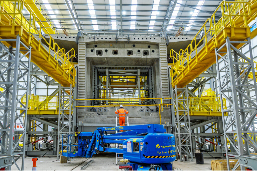
To minimise construction traffic on local roads, the jetties built across the lakes provide a continuous road inside the project. The 140-tonne viaduct segments are made on site at a large purpose-built temporary factory close to the north abutment. This also reduces road movements as does the use of dedicated slipways on the M25 for construction traffic. At peak construction, this factory casts around 12 segments every week using a ‘match-casting’ technique in which each segment is poured against the previous one to ensure the whole deck fits perfectly.
A 700-tonne launching gantry positions the segments. This is 160 metres long, 18 metres high and 18 metres wide. It was originally built in 2004 and had been used in Hong Kong and Singapore. After it arrived in the UK in 49 containers, it took several months to assemble. Prior to its use it had to be assessed against applicable UK standards, including those for wind loading. Using this gantry determined the maximum segment weight and hence the number of segments required.
The gantry has two long trusses with two moveable main and secondary base supports. Between the trusses are trollies and cranes for it to simultaneously place segments either side of a pier. It uses its supports to advance over the already completed bridge deck so that its truss can extend to the next pier. It then positions a single segment on top of this pier on which one of its main supports is then placed.
Single segments are then placed either side of this pier. Props are secured under these segments and the gantry anchored to the pile cap before further segments can be placed. This increases the stabilising lever arm from two to six metres to resist the bending moment from placing further segments away from the piers. These then form an even cantilever either side of the pier. Epoxy is applied to the face of each segment as it is positioned after which the cantilever is temporarily tensioned to compress the epoxy whilst it sets. Once the span’s final segment is inserted, it is post tensioned with permanent steel strands. At peak rate, the gantry can position six segments per day.
The viaduct’s construction began in early 2021 when the first piles were installed. The last of its 292 piles were installed in January 2023. By then, 500 metres of the viaduct had been completed after the launching gantry commenced operation in spring 2022. As of February, over 700 of its 1,000 deck segments have been installed.
The installation of track and railway systems which start after construction of this 3.4km-long viaduct will be completed in 2025. It will then have stolen the title of the UK’s longest railway bridge from Dundee’s Tay Bridge by 100 metres.
Double composite viaducts
The 450-metre Wendover Dean and 345-metre Small Dean viaducts near Wendover have respectively nine and five piers, giving them average spans of 45 and 57.5 metres. Though successfully used in Europe, these viaducts are two of five HS2 viaducts that are the first in the UK with an innovative double composite design. This is described in an HS2 learning legacy technical paper by Razvan Capra, Pere Alfaras Calvo, and Paul Van Hagen of Acardis/EKFB.
For over a hundred years, steel-concrete composite bridges have been built with a top concrete slab in compression and a steel structure resisting tensile forces. However bending moments over intermediate piers can cause the concrete slab to crack unless there is sufficient steel reinforcement to control the tension forces.
The double composite section design adds a concrete slab to the lower part of the structure around its piers. This reduces the structural steel required by 10 to 15% and simplifies steel fabrication. There has recently been increased interest in this new form of construction as high-speed railway projects benefit from it.
These HS2 viaducts have an in-situ reinforced concrete slab over the pier regions. Outside this area there are precast concrete planks connected by an in-situ stitch pour. This provides increased damping and enhances the superstructure’s torsional resistance. For high-speed rail, this provides an improved dynamic response and limits noise from wheel-track induced vibrations. The resultant closed box section also creates a suitable enclosure for services and drainage.
Although they offer significant advantages, such bridges require additional construction stages for their in-situ concrete slabs and precast planks. They also add to the weight of the superstructure which may require bigger bearings and might slightly increase the viaduct’s cost.
A particular construction advantage is that the deck is launchable and so can be built at ground level and pushed over its piers. This allows the use of more factory-built precast sections and reduces working at height.
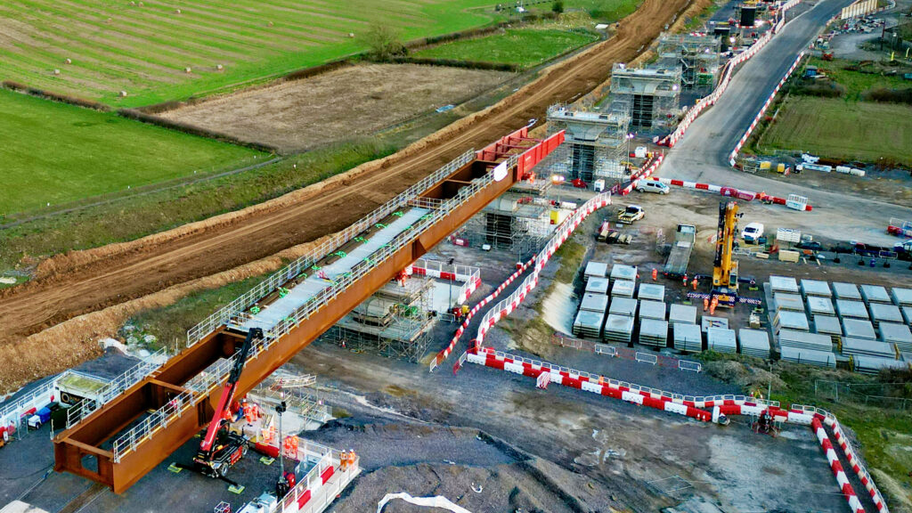
The first bridge slide of the Wendover Dean viaduct took place in January when 90 metres of bridge beam was slid over Teflon pads at nine metres per hour onto its first two piers. Due to its length, the deck is being assembled in three sections with each one pushed out before the next section is attached behind it. The deck’s steel girders are delivered to site in 25-metre lengths which are welded together on the assembly platform. As the deck is slid over, it bends under its own weight. An angled beam fitted to the front of the deck raises it when it reaches the next pier.
The piers consist of a stem with a hammerhead on top. The stem is constructed by first installing a steel reinforcement column, then placing a pre-cast shell around it before pouring the concrete. Then, a 50-tonne pre-cast hammerhead shell is placed on top of the stem, a reinforcement cage is lifted into it and concrete is poured into it.
Construction of the Small Dean viaduct is less advanced. This requires piers to be built between the Chiltern main line railway and A413 road which needs to be diverted to accommodate the piers.
Other double composite viaducts are being constructed at Westbury (320 metres), Turweston (70 metres) and Lower Thorpe (210 metres).
Video of Westbury viaduct slide
Modular viaducts
The 880-metre Thame Valley and 515-metre Edgcote viaducts have respectively 34 and 20 piers giving them both average spans of around 25 metres, i.e. half that of the double composite viaducts.
These are the first UK viaducts to have all their major components manufactured off site. The Thame Valley viaduct requires 68 x 42-tonne fully formed pier sections and 72 x 97-tonne deck beams together with parapet and ancillary beams. On site, the pier sections are plugged into their pile caps. Once the beams have been placed on the pier tops, they are braced until the deck slab is cast which is the only substantial in-situ concrete required. After this parapet beams are fitted.
The pretensioned hollow beams are coupled to each other through thickened end walls using post tensioned bars. In this way a continuously tensioned deck is created, with all main elements of the structure always in compression.
As well as improving site safety, the factory production of such enormous parts enables work to be done to millimetre tolerances. This is also expected to save around five months construction time.
Delta junction viaducts
Just north of HS2’s Birmingham Interchange station is the triangular Delta junction where HS2 trains from London will be routed to Birmingham or the West Coast Main Line (WCML).
The junction has 10km of HS2 tracks with 13 viaducts crossing a network of motorways, local roads, railways, and rivers.
The junction’s west chord has the River Cole east and west viaducts and the M42/M6 link viaducts which had the first part of the first deck slid into position in February. Its full 158-metre composite deck will be positioned in April.
The east chord has Coleshill North and South Viaducts, Watton House viaducts and the River Tame East and West viaducts. The first 39-metre span of the 472-metre River Tame West viaduct was completed in December.
The north chord has the separate single-track Water Orton northbound and southbound viaducts which, at up to 20 metres high, will be amongst HS2’s tallest structures. These two 700-metre-long viaducts will be supported on 32 piers, the first of which was completed in August.
A total of 153 piers will be built for the Delta Junction’s viaducts. Of these, 15 were completed by the end of 2023. There are three types of viaducts:
Precast segmental viaducts with 45-metre standard spans (River Tame East and West; Water Orton 1 and 2; Coleshill East and West).
Composite viaducts having concrete decks and weathered steel structures with standard spans of more than 45 metres (M42/M6 Link Road East and West; River Cole East and West).
Low viaducts with standard spans of 25 metres with standard concrete deck and precast beams. (M42 Coleshill North and South; Watton House).
A 55,000 sq. m factory at Kingsbury employing 1,000 people started producing concrete viaduct segments in June. This will produce the delta junction’s 2,742 segments which weigh between 50 and 80 tonnes at a rate of eight per day.
Into Birmingham
The last two kilometres to HS2’s Birmingham Curzon Street station are on five connected viaducts: Duddeston Junction viaduct; Curzon Street viaducts numbers 1, 2, and 3, and the Lawley Middleway viaduct.
After passing the HS2’s Washwood Heath depot, the line crosses the Derby to Birmingham railway at Duddeston junction on a 370-metre-long viaduct with a 1 in 33 gradient to connect it to the 690-metre Curzon No 1 viaduct which will be 30 metres high where it crosses the River Rea. From this point, the line drops at 1 in 200 to Curzon Street Station.
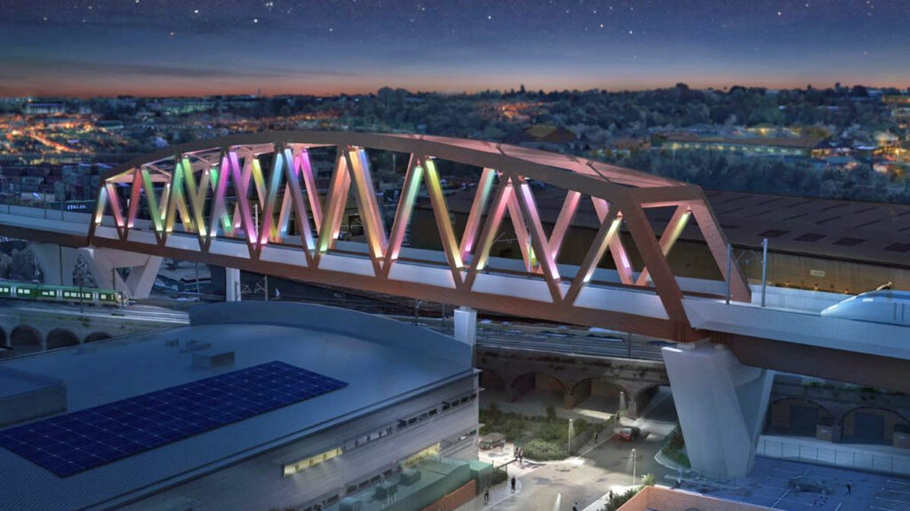
The 150-metre-long Curzon No 2 viaduct has a 25-metre- high truss in weathering steel incorporating dynamic colour lighting. This will be 40 metres above ground level as it crosses the Birmingham and Bushbury railway which is on a 15-metre-high brick viaduct.
The 213-metre Lawley Middleway viaduct between Curzon No 2 and Curzon No 1 viaducts widens out at its western end for the start of the Curzon Street station throat. The 300-metre Curzon No 3 viaduct is around 5 metres above ground level and widens into four separate decks on V piers to accommodate most of the station throat. This arrangement maximises daylight and space in the public area below. Where it crosses the Digbeth Canal, this viaduct has four inverted steel piers to reference Birmingham’s canal heritage.
Work on Curzon No 3 viaduct is well advanced. Its first V pier was completed in January 2023. By November, its first two 90-metre decks and 26 piers had been completed.
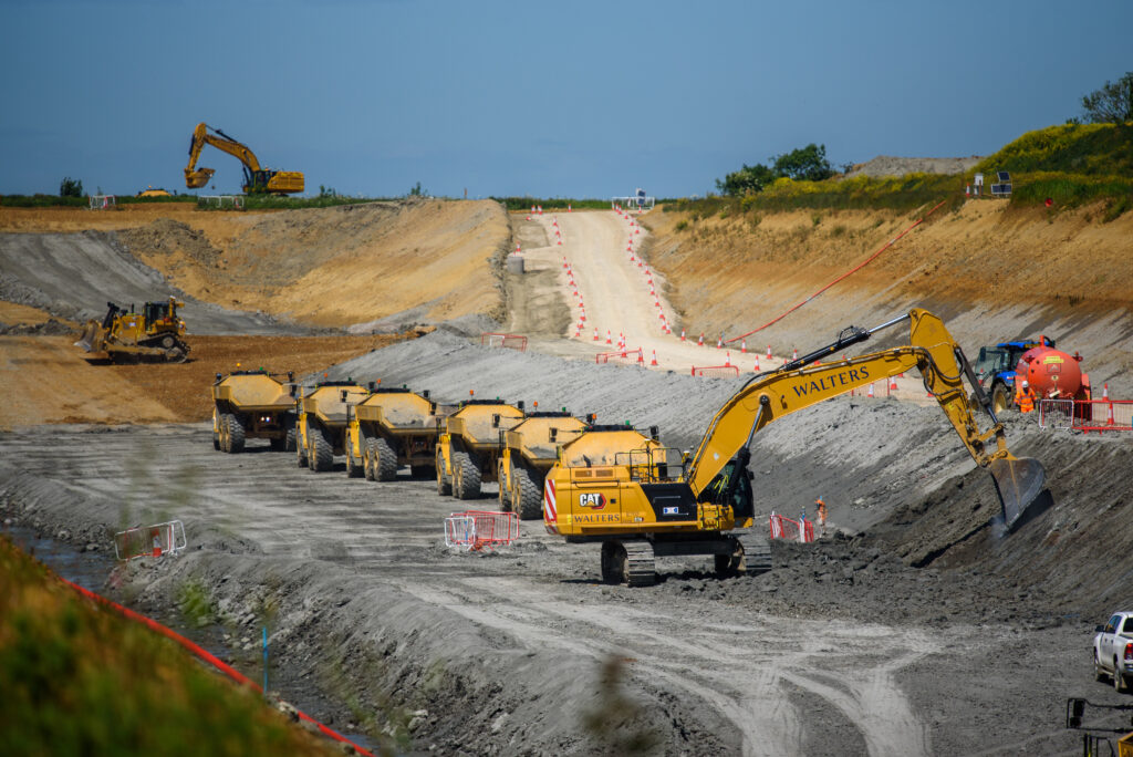
Earthworks
Whilst not so newsworthy or visually striking, HS2’s earthworks are a huge undertaking that present significant challenges. Phase 1 requires around 50 embankments of which the longest is at Grendon Underwood which is 3km long and up to 3.5 metres high. Sixty-six cuttings are required, of which the longest is the 4.1km Calvert cutting. The 750-metres-long, 30.5-metres-deep Lower Thorpe cutting is HS2’s deepest. Tens of millions of cubic metres have been excavated to create HS2’s cuttings of which 95% were reused on site.
Work to prepare the 65-hectare site at Washwood Heath for HS2’s train maintenance depot and control centre was completed in December. This heavily contaminated derelict site required over a million cubic metres of excavations which included rubble from demolished car factories and other industrial plants. Excavations were up to seven metres deep and were remediated by screening and bio-remediation to remove oils and fuel contamination. This enabled all excavated materials to be reused on site, which eliminated the need to import and export aggregate materials and saved 54,400 HGV movements on local roads.
The reuse of excavations between the Chiltern and Long Itchington Wood tunnels is described in another learning legacy paper by EKFB’s environmental design manager, Zara Rostance. This explains the use of the Definition of Waste Code of Practice (DoWCoP) managed by CL:AIRE (Contaminated Land: Applications in Real Environments), a charity committed to supporting all those involved in sustainable land reuse. The DoWCoP sets out good practice when assessing if materials are to be classified as waste and determining when treated waste can cease to be waste for a particular use.
In HS2’s central section, it is estimated that there have been 35 million cubic metres of excavations of which made ground (any material affected by people) is approximately 1 million cubic metres. The most significant challenge is re-locating natural materials with distinct chemical fingerprints and leaching characteristics to geologically contrasting environments. This requires a detailed assessment of materials management at the scheme design and applying the four DoWCoP acceptance criteria as follows:
Protection of human health and environment – Advising site teams of constraints using graphical information systems with layers showing local wildlife, archaeological sites, and made ground. Regular meetings were held to inform the Environment Agency (EA) and CL:AIRE of site activities and project requirements.
Suitability of use – Zoning system agreed with the EA for re-use of made ground according to geology, aquifer classification, proximity to surface water and human health. Summarised Earthworks Quantity Schedules showing quantity and types of material in a section were compared with area material requirements.
Certainty of use – gaining HS2 Act schedule 17 consent for landscaping specification well in advance of the work to provide certainty of where material can actually be re-used.
Quantity required – Using EKFB’s DIGGER (Digital Graphical Earthworks Reporting) automated material tracking system to monitor excavated material movements from the place of origin to the final destination. This uses various data streams including GPS excavator trimble tracking and drone surveys to create a digital 3D earthworks model.
Reducing imported materials in this way reduces HS2’s carbon footprint. In 2022, the reuse of 25.6 million tonnes provided a reduction of 2.5 million HGV movements. Zara concluded her paper by emphasising the importance of effective engagement with the EA, local authorities, and CL:AIRE.
Leaving a legacy
The London and Birmingham Railway’s (L&BR) proposal to build the world’s first long distance inter-city railway was the subject of much opposition and turbulent meetings in towns along the route. After a failed attempt, it eventually got its Act of Parliament approved in 1833. For its day, building the line was comparable to HS2. Twenty thousand men worked on it for five years and it required the movement of 12 million cubic metres of material.
When the line opened in 1838, there were six trains a day between the two cities and the train journey took five-and-a-half hours. This line’s legacy was demonstrating the feasibility and desirability of building railways between population centres, not least because of the economic activity they generate. This is still the case today as shown by the volume of freight and passenger traffic carried by the bottom part of the WCML which would have astounded the L&BR’s promoters.
Over almost 200 years, the London to Birmingham railway has been developed into one of Europe’s busiest rail corridors. In contrast, HS2 was designed as a high-capacity railway from the start. Although Government has chosen not to use this capacity, HS2 will offer Birmingham significant benefits which already include a large increase in inward investment. Hopefully, at some time in the future the decision to deny other cities the benefits of high-speed rail may be reversed as its benefits become more generally accepted.
HS2’s other legacies will include adding to the UK’s iconic railway structures. The care taken to ensure its structures fit into the landscape includes specifying that bridge design teams must include an architect.
The project has also shown how major construction projects can reduce embodied carbon and use innovative designs that also offer environmental and safety benefits. Its Learning Legacy website has almost 200 papers which describe innovations and lessons learned with the aim of passing on new knowledge to improve UK productivity.
A significant legacy is building a diverse, skilled, and talented workforce across the project’s supply chain, of which 4% are apprentices. The intention is that this workforce will benefit the UK infrastructure industry for years to come.
Thus, despite being curtailed with reduced benefits, there is no doubt that HS2 will leave a lasting legacy.
Lead image credit: HS2